

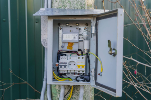
An intelligent earthing switch controller manages electrical and mechanical commands for an earthing switch. It connects operating instructions with actuators, sensors, interlocking circuits, and monitoring equipment. Unlike a basic manual mechanism, it can process operating conditions before allowing a switching action. The controller may receive commands from a local panel, remote control system, or automated station system. It then checks predefined conditions and sends an appropriate signal to the operating mechanism. Position feedback confirms whether the switch reached the requested state. Additional signals can report control power, mechanism faults, communication status, and operating mode. This coordinated process helps create a controlled relationship between command, operation, verification, and status reporting. Engineers therefore consider the controller as part of a wider secondary control system rather than an isolated switching device.
Why Is Intelligent Control Important in Electrical Switchgear?
Modern electrical switchgear often combines switching equipment with protection, measurement, communication, and automation functions. Earthing operations require particular attention because the switch establishes a conductive path to earth. Incorrect operation can create serious electrical and operational consequences. Intelligent control helps apply predefined conditions before an operating command reaches the actuator. Local and remote control modes can also be separated through dedicated selection logic. Position feedback provides another important layer because a command alone does not prove that the physical switch moved correctly. Alarm signals can identify abnormal conditions when the mechanism fails to complete an operation. These functions support safer operating procedures while giving operators clearer information about equipment status. The actual protection level still depends on the complete switchgear design, interlocking scheme, protection system, and operating procedures used at the installation.
How Does An Intelligent Earthing Switch Controller Process Commands?
An intelligent earthing switch controller normally follows a sequence rather than sending every command directly to the actuator. First, the system receives an operating request from an authorized source. Next, the control logic checks the selected operating mode and relevant interlocking conditions. The controller may also verify that the required control power remains available. If all required conditions are satisfied, an output signal activates the appropriate actuator circuit. Position switches or auxiliary contacts then return feedback to the control system. If the expected position does not appear within the configured operating period, the controller can generate a fault condition. This sequence creates a closed control loop. The command starts the process, while feedback confirms its physical result. Such logic also helps prevent repeated commands when the mechanism remains in an abnormal state.
What Components Work Inside the Control System?
A typical intelligent control arrangement contains several functional elements that cooperate during switching operations. The processing unit executes programmed logic and evaluates incoming signals. Digital inputs receive information from auxiliary contacts, selectors, interlocks, and protection-related interfaces. Digital outputs control relays, contactors, or actuator circuits. Communication interfaces transfer status and alarm information to higher-level automation equipment. Some installations also include dedicated monitoring circuits for control voltage and mechanism conditions. Relay interfaces can provide electrical isolation between low-level control electronics and external circuits. Terminal blocks connect field wiring with the internal control system and simplify commissioning work. Depending on the switchgear design, additional modules may support event recording or diagnostic functions. Each component has a defined role, so engineers should evaluate the complete signal path rather than selecting a controller based only on its processor or communication interface.
How Do Interlocking Functions Protect Earthing Operations?
Interlocking prevents selected operations when required electrical or mechanical conditions do not exist. For example, the control circuit may block an earthing operation when another switching device remains in an incompatible position. Mechanical interlocks can physically restrict movement, while electrical interlocks use contacts and control logic to interrupt command circuits. A properly coordinated system can use both methods to provide multiple barriers against incorrect operation. The exact conditions depend on the switchgear arrangement, voltage level, operating sequence, and safety philosophy. Engineers should define these conditions from the electrical single-line diagram and control schematic. An interlock should also provide a clear status signal where practical. Operators then have better information about why a command cannot proceed. Effective interlocking is therefore not simply a software function. It combines equipment design, electrical circuits, mechanical mechanisms, and clearly defined operating procedures.
How Does the Controller Confirm Switch Position?
Position confirmation provides essential feedback after an operating command. Most switchgear arrangements use auxiliary contacts or dedicated position switches connected to the control circuit. These devices change electrical state according to the physical position of the earthing switch mechanism. The controller interprets these signals and reports the corresponding status to local or remote equipment. A reliable system should distinguish between an open position, closed position, and abnormal or intermediate condition where applicable. Feedback timing also matters because mechanical movement requires a finite operating period. If the expected signal fails to appear, the system can issue an alarm instead of reporting successful operation. Engineers should verify both electrical feedback and actual mechanical movement during commissioning. This prevents a situation where a control system displays a normal status while the physical mechanism remains incorrectly positioned. Position monitoring therefore forms a critical link between command execution and operational confirmation.
What Role Does Communication Play in Intelligent Grounding Control?
Communication allows switching status and operating information to move between field equipment and higher-level automation systems. A controller may exchange position, alarm, operating mode, and diagnostic information with station control equipment. Remote operators can then view equipment status without relying entirely on local inspection. Communication also supports event recording and centralized alarm management when the surrounding automation architecture provides these functions. However, communication does not replace local interlocking or physical safety mechanisms. A network failure should not automatically create permission for an otherwise prohibited operation. Engineers should define what happens when communication becomes unavailable, delayed, or inconsistent. The controller should retain appropriate local operating logic even when supervisory communication is interrupted. Interface selection also depends on existing station architecture, wiring arrangements, protocol requirements, and cybersecurity practices. A practical design therefore considers communication as one layer within a broader control structure.
How Does Local and Remote Operation Differ?
Local operation normally gives personnel direct access to the switchgear control interface. Remote operation allows commands to originate from a supervisory or station automation system. Both modes require clearly defined authority and operating conditions. A local or remote selector can determine which command source has control at a particular time. Maintenance activities may require local control while remote commands remain blocked. Conversely, normal unattended operation may use remote commands when the installation supports that operating mode. The control system should make the active mode visible to operators. Clear status indications reduce confusion when personnel work around energized or isolated equipment. Remote capability also depends on communication availability and the correct configuration of the supervisory system. These functions should be tested separately during commissioning. Engineers need to verify command priority, mode switching, feedback behavior, and blocking conditions under both normal and abnormal circumstances.
What Signals Should an Intelligent Controller Monitor?
An intelligent control system can monitor several signals that describe equipment condition and operating availability. The exact signal list depends on the switchgear configuration and required automation functions. Typical signals include:
- Earthing switch open or closed position
- Motor or actuator operating status
- Control power availability
- Local or remote operating mode
- Interlock status
- Operation timeout or mechanism fault
- Communication status
- Auxiliary contact feedback
These signals provide more useful information than a simple open-or-closed indication. For example, control power status can help distinguish an unavailable mechanism from an incorrect operating command. An operation timeout can indicate that movement did not finish within the expected period. Interlock status can also help operators identify why a command remains blocked. Engineers should define signal priorities according to operational needs. Critical conditions should produce clear alarms, while routine states can remain available through normal status monitoring. Proper signal selection improves both operation and subsequent fault investigation.
How Can an Intelligent Earthing Switch Controller Handle Faults?
Fault handling begins with detecting conditions that differ from the expected operating sequence. A controller can monitor operation duration, position feedback, control power, and selected mechanism signals. If an actuator receives a command but the expected position does not appear, the system can generate an operation fault. Communication loss can also produce a separate status condition without necessarily affecting local control logic. Control power failure requires different treatment because the mechanism may become unavailable before any command reaches the actuator. Repeated automatic commands should not occur simply because feedback remains unchanged. Such behavior could increase mechanical stress or create confusing operating conditions. Instead, the control philosophy should define clear fault states and require appropriate operator intervention. Alarm records can then help maintenance personnel trace the sequence of events. The exact response must follow the equipment design and approved operating procedures.
Which Electrical Conditions Should Be Checked Before Operation?
Before an earthing operation, the control system may need information about the positions of associated switching devices. Relevant conditions can include isolator status, breaker status, interlock states, control mode, and other signals defined by the switchgear design. Some installations may also require confirmation that a circuit has reached the required electrical condition before earthing becomes permissible. The controller should only evaluate signals that its architecture can reliably receive and interpret. It should not be treated as a substitute for protection relays, voltage detection equipment, or other dedicated safety systems. Engineers should map each permissive condition to a specific circuit or signal source. This approach makes the control logic easier to verify during testing. Clear documentation also helps maintenance teams identify the reason for an operation block. Correct permissive logic depends on the complete electrical design rather than a universal list of conditions.
How Should an Intelligent Earthing Switch Controller Be Selected?
Controller selection should begin with the actual requirements of the switchgear rather than with a generic feature list. Engineers should verify the available control voltage, required input and output points, actuator characteristics, installation space, and environmental conditions. Communication requirements should match the existing station automation architecture. The number and type of position feedback signals also need careful consideration. Electrical isolation between control circuits may be necessary where field conditions require it. Response timing, diagnostic functions, and alarm handling can affect commissioning and maintenance work. Mechanical compatibility is equally important because the controller must operate the specified actuator correctly. Documentation should clearly describe terminal assignments, wiring requirements, operating logic, and fault indications. Engineers should also review how the equipment performs under expected temperature, humidity, vibration, and electromagnetic conditions. A complete selection process therefore combines electrical, mechanical, communication, environmental, and maintenance requirements.
What Installation Details Affect Controller Reliability?
Installation quality can strongly influence the long-term behavior of a control system. Control wiring should follow the approved schematic and maintain clear separation where required between different circuit categories. Terminal connections need secure mechanical fastening and correct identification. Communication cables may require appropriate routing and shielding to reduce electromagnetic interference. Control power should remain within the equipment’s specified operating range. Grounding arrangements must also follow the applicable switchgear and site requirements. During installation, engineers should verify auxiliary contact wiring because incorrect position feedback can produce misleading system status. Field testing should cover command outputs, feedback inputs, interlocks, alarms, and communication points. Mechanical movement should also be observed rather than relying only on electrical indications. These checks establish whether the complete installation performs as intended. Reliable operation comes from coordinated hardware, wiring, software logic, field adjustment, and commissioning practices rather than from the controller alone.
What Should Engineers Verify During Commissioning?
Commissioning should verify the complete operating sequence from command source to physical movement and final feedback. Engineers can begin by checking control power and terminal wiring against approved documentation. Input testing should confirm every relevant auxiliary contact and interlock signal. Output testing should verify that each command reaches the intended actuator circuit. Position tests should confirm that displayed status matches actual mechanical position. Remote communication should then be tested separately from local operation. Fault scenarios should also receive attention, including missing feedback, control power interruption, communication loss, and operation timeout. Each abnormal condition should produce the expected status or alarm. Testing should also confirm that prohibited operations remain blocked under defined interlock conditions. Final commissioning records should document test results, deviations, and corrective actions. This evidence creates a useful reference for future maintenance. A complete commissioning process therefore validates the entire control chain rather than testing the controller as a standalone device.
FAQWhat Is the Main Function of an Intelligent Earthing Switch Controller?
An intelligent earthing switch controller coordinates commands, operating conditions, actuator control, and position feedback. It can receive a local or remote command and evaluate predefined permissive conditions before activating the operating mechanism. Feedback circuits then confirm whether the physical switch reached the requested position. Additional functions may include alarm handling, operating-mode selection, communication, and fault monitoring. The controller does not normally replace protection relays or dedicated electrical safety equipment. Its role depends on the complete switchgear architecture and control philosophy. Engineers should therefore evaluate its interfaces with auxiliary contacts, interlocking circuits, actuators, and station automation systems. Correct configuration is essential because the controller must reflect the actual operating sequence of the equipment.
Can an Intelligent Controller Support Remote Earthing Switch Operation?
Remote operation can be supported when the controller, actuator, communication system, and switchgear control philosophy are designed for that function. A remote command normally passes through defined permission checks before reaching the operating circuit. The system should also return position and fault information after the operation. Local and remote modes require clear authority rules so that maintenance personnel can prevent unintended remote commands. Communication failure should have a defined response and should not bypass required interlocking conditions. Remote functionality also depends on the station automation system and its configured interfaces. Engineers should test remote commands separately from local commands during commissioning. Successful remote control therefore requires coordinated hardware, communication, interlocking, feedback, and operating procedures.
What Should Be Checked Before Installing an Intelligent Controller?
Engineers should first verify the switchgear control voltage, actuator type, required input and output signals, installation dimensions, and environmental conditions. Position feedback requirements should match the available auxiliary contacts or position switches. Interlocking circuits also need careful review because their logic must correspond with the actual switching sequence. Communication interfaces should match the existing automation architecture where remote monitoring or control is required. Wiring diagrams and terminal assignments should be available before installation begins. Field conditions such as electromagnetic interference, temperature, humidity, and vibration may also affect equipment selection. Finally, commissioning requirements should be defined in advance. Checking these factors before installation reduces wiring changes and logic conflicts during field testing.